Refractory materials and related technologies for refining furnaces are crucial for ensuring the smooth execution of the refining process and the quality of the refined steel. Although refining methods and operational practices vary, the conditions to which ladle linings are subjected share many common characteristics. These include exposure to high-temperature vacuum environments, chemical interactions with slags of widely varying basicity, intense mechanical impact from molten steel, slag, and gas flow, as well as thermal stress from electric arcs and severe thermal shock.
Consequently, the development of high-quality refractory materials—characterized by high-temperature resistance, erosion and abrasion resistance, thermal shock resistance, and stability under high-temperature vacuum conditions—is vital for extending the service life of furnace linings, producing clean steel, and reducing production costs.
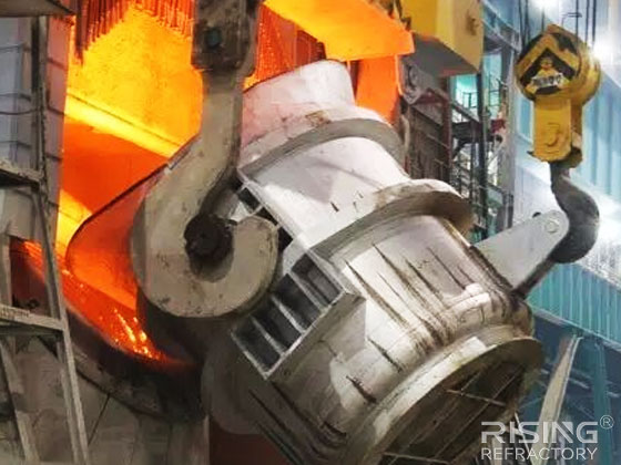
Refractories for Ladle Refining Units
Refractories for LF (Ladle Furnace) / VLF (Vacuum Ladle Furnace) Units
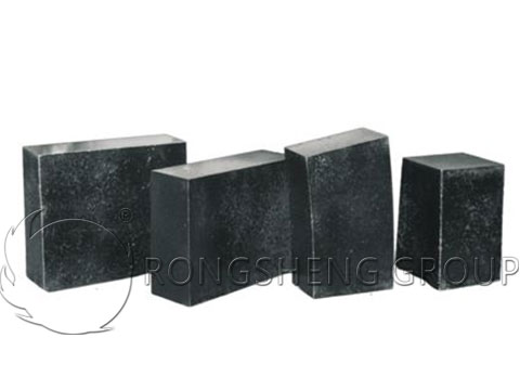
- Refractories for the Slag Line: The slag line area is subjected to highly basic slag and high-stress conditions, leading to severe degradation. Consequently, high-quality magnesia-carbon (MgO-C) bricks—which offer excellent resistance to both corrosion and thermal shock—are predominantly used.
- Refractories for the Sidewall: High-alumina bricks are typically used for the sidewalls of LF units. However, while traditional high-alumina bricks possess good corrosion resistance, they are prone to significant slag penetration. This penetration causes structural spalling and inconsistent durability; furthermore, the shrinkage of the slag-penetrated zones leads to the formation of cracks, accelerating wear. To address this, a specific amount of magnesia (MgO) is added to the refractory mix; the expansion that occurs during the formation of spinel (magnesium-aluminate spinel) upon heating helps prevent cracking. Additionally, incorporating approximately 10% carbon and a measured amount of pre-synthesized magnesium-aluminate spinel further enhances the corrosion resistance of the bricks.
Refractories for ASEA-SKF Ladle Refining Units
The ASEA-SKF refining process was jointly developed by the Swedish companies ASEA (Allmänna Svenska Elektriska Aktiebolaget) and SKF (Svenska Kullagerfabriken). This system integrates several functions, including low-frequency electromagnetic stirring, electric arc heating at atmospheric pressure, vacuum degassing, slag-based refining, and vacuum oxygen decarburization. Currently, this refining method is applied to heat sizes ranging from 20 to 260 tons, with additional capabilities for powder injection and argon stirring.
In the ASEA-SKF process, desulfurization is typically carried out using neutral or highly basic slag. For the slag line, materials such as magnesia-carbon, magnesia-chrome, pure magnesia, or magnesia-dolomite bricks are employed. The sidewalls and the ladle bottom are lined with high-alumina bricks (containing 75% Al₂O₃), while the area below the molten steel line often utilizes alumina-carbon bricks. In cases where desulfurization is not required, the current trend is to use high-quality high-alumina bricks (with an Al₂O₃ content exceeding 85%) for the slag line, and castables for the ladle bottom.
Refractories for Stainless Steel Refining Units
- Refractories for VOD (Vacuum Oxygen Decarburization) Refining
A VOD unit is essentially similar to a ladle degassing unit, with the key difference being the insertion of an oxygen lance through the center of the vacuum chamber lid for oxygen blowing and decarburization. For the VOD refining furnace lining, magnesia-chrome bricks or magnesia-calcia bricks are used at the slag line. The side walls are typically lined with magnesia-chrome or magnesia-calcia bricks, while the bottom is lined with magnesia-chrome or high-alumina bricks.
- Refractories for AOD (Argon Oxygen Decarburization) Refining
The design of an AOD vessel is similar to that of a basic oxygen furnace (BOF) converter, having evolved from an offset-mouth configuration to a straight-mouth design, which facilitates easier brick lining. The vessel is supported by trunnions, allowing it to be tilted to any desired angle. During the AOD smelting process, the composition and properties of the slag fluctuate significantly; the basicity shifts from a low level of approximately 0.6 in the initial slag to a high level of 4.0–4.5 or even greater. At high temperatures, the refractory lining is subjected to severe corrosion by this highly aggressive basic slag. In the United States and the United Kingdom, magnesia-chrome bricks are primarily used for AOD linings. In China and various European countries, there has been a greater focus on developing magnesia-calcia bricks and dolomite-based bricks with tailored carbon content. In terms of material specifications, high purity and low impurity levels are required.
Refractories for RH/RH-OB Vacuum Treatment Units
The circulating degassing process, developed jointly by the German companies Ruhrstahl and Heraeus in 1958, is known as the RH process. The RH-OB process is an enhancement of the RH refining method, designed specifically to compensate for heat loss in the molten steel.
The refractory lining of an RH unit operates under vacuum-sealed conditions. Typical service conditions involve high temperatures (approximately 1600°C), thermal cycling (with fluctuations of up to 600°C), pressure cycling (ranging from atmospheric pressure down to 66.66 Pa), high-velocity molten steel flow, and exposure to corrosive slag and molten iron oxides. The RH-OB process, which incorporates oxygen blowing, enhances degassing capacity and intensifies the splashing of molten steel within the vacuum vessel; this strengthens the refining operation but also significantly accelerates the degradation of the refractory materials.
For the vacuum vessels of RH/RH-OB units, materials such as magnesia bricks, magnesia-chrome bricks, high-alumina bricks, and high-alumina castables are typically employed. These refractories must possess a robust combination of properties, including resistance to corrosion and thermal shock.
Structure of Electric Smelting Furnaces for Non-Ferrous Metals and the Refractory Bricks Used Internally
In the smelting of non-ferrous metals, electric furnace smelting utilizes electrical energy to melt materials—either through an electric arc generated between electrodes and the furnace charge, or by using molten slag as a resistive medium to produce high temperatures. The temperature of the melt can be precisely controlled anywhere within the range of 1200°C to 1600°C. Electric smelting furnaces are primarily used for processing materials that contain high proportions of refractory gangue components; in regions with abundant electrical power, they are also employed for smelting conventional ores.
The key advantages of electric furnace smelting include: ease of temperature regulation within the molten bath, the ability to reach high temperatures, a low theoretical volume of off-gas, high thermal efficiency (reaching 60%–80%), a smaller volume of slag, and a high overall recovery rate for the metals being smelted.
The primary drawbacks are: high electrical energy consumption, higher processing costs compared to reverberatory furnace smelting, a strict requirement that the moisture content of the furnace charge generally not exceed 3%, and relatively higher capital investment for infrastructure.
In China, electric furnaces are utilized in the smelting of metals such as copper, nickel, zinc, and tin, as well as for the thermal insulation and depletion (metal recovery from slag) of molten slag. Drawing on the furnace structure and operating environment of electric furnaces used for smelting copper and nickel concentrates, Rongsheng Refractories outlines the specific types and characteristics of the refractory bricks required for these applications.
Furnace Types for Electric Smelting
Electric furnaces used for smelting copper sulfide concentrates and copper-nickel sulfide ores can be rectangular, elliptical, or circular in shape.
In non-ferrous metal smelting, large-scale electric furnaces are typically of the stationary, rectangular, and enclosed type. Rectangular furnaces offer a larger hearth area and higher power capacity, facilitate optimal transformer configuration, promote the separation of matte from slag, and allow for convenient construction of the furnace lining.
Rectangular furnaces range from 10 to 35.66 meters in length and 4.5 to 10.67 meters in width. The slag temperature is maintained between 1200°C and 1380°C. The final smelting products—either copper-nickel matte (an alloy of nickel, copper, and iron) or copper matte—are produced at temperatures ranging from approximately 1050°C to 1250°C, with the production process operating continuously.
Furnace Structure
The furnace structure consists of refractory masonry, a steel framework, and foundation piers. The furnace bottom is supported by these piers, creating an elevated structure. Because the temperature at the bottom of an electric smelting furnace is higher than that of a reverberatory smelting furnace, the refractory masonry—comprising the furnace bottom, side walls, and roof—is designed to protect the furnace base.
(I) Furnace Bottom
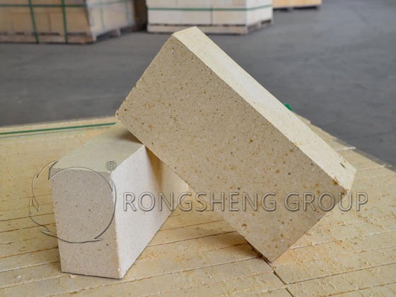
The bottom of an electric smelting furnace is constructed as an inverted-arch masonry structure, typically consisting of 2 to 3 layers of arch bricks, with a total thickness generally ranging from 1250 to 1300 mm. From bottom to top, the layers are: a steel bottom plate (40 mm), a layer of castable refractory (95–150 mm), fireclay bricks (230–300 mm), and a top layer of magnesite bricks (760 mm). Alternatively, the castable refractory may be omitted, with the inverted-arch base formed by laying fireclay bricks (500 mm) topped with magnesite bricks (760 mm).
In industrial practice, this structural design has proven problematic, with the following primary drawbacks:
- (1) The lower portion of the furnace bottom is constructed as a monolithic, inverted-arch base made of castable refractory. This design is higher at the sides and lower in the center, where the thickness is reduced to only 150–200 mm. Such a significant variation in thickness renders the monolithic base incapable of supporting the 1000–2000-ton weight of the furnace; furthermore, it cannot accommodate differential thermal expansion or uneven settlement. This leads to the fracturing of the castable refractory base, resulting in furnace leakage.
- (2) The interface between the side walls and the furnace bottom features a straight vertical joint, which frequently develops linear cracks during operation, again leading to furnace leakage.
To improve the design, the original castable refractory base has been replaced with an inverted-arch base constructed from fireclay bricks. Additionally, the straight vertical joint at the junction between the arch skewbacks and the furnace walls has been replaced with a stepped (staggered) masonry joint. Furthermore, clay bricks laid using the wet method must be dried before the magnesite brick inverted arch is constructed. If the clay brick layer and the magnesite brick inverted arch are dried together, moisture rising from the base will cause the overlying magnesite bricks to pulverize.
(II) Furnace Walls
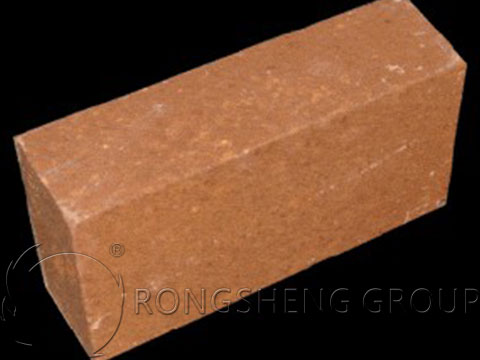
For electric furnaces used to smelt copper concentrates or copper-nickel concentrates, the furnace walls are typically no more than 8.7 meters high. The inner surfaces of the side walls and main end walls—specifically the sections below the slag line—are constructed using magnesite bricks, while the inner surfaces above the slag line and the entire outer surfaces are built with fireclay bricks. The side walls consist of 690 mm of magnesite brick and 114 mm of fireclay brick, while the end walls consist of 920 mm of magnesite brick and 114 mm of fireclay brick. In large rectangular electric furnaces, the furnace lining is secured by a combination of a steel shell (composed of 20–40 mm thick steel plates) and a structural framework. In recent years, to extend the service life of the lining at the slag line, some large electric furnaces have incorporated water-jacketed panels, which serve both as a structural shell and as a water-cooling system for the furnace walls.
(III) Furnace Roof
During the smelting process in an electric furnace, the electrodes are submerged in the slag. An electric current passes through the slag, heating it and using it as the primary heat source for smelting. Consequently, only a minimal amount of reaction gases and water vapor is released from the molten mass. Furthermore, since the surface of the slag is largely covered by the furnace charge (feed material), the temperature of the furnace roof during operation does not exceed 600°C. Furnace roofs constructed with fireclay bricks have proven to be highly effective.
Furnace roofs are generally constructed using fireclay bricks. For large electric furnaces, the roof is typically 300–400 mm thick; in some cases, a layer of insulating bricks is added to reduce heat loss. The span of such roofs is approximately 5.3–6.2 meters. For smaller electric furnaces, the roof thickness is 230 mm. If large openings are required in the roof, the surrounding areas are cast as a single, integrated structure using refractory castables. Alternatively, some furnace roofs are constructed by ramming refractory castables or by embedding water-cooled copper pipes into precast refractory castable sections; these designs offer superior structural integrity and sealing compared to roofs built from individual bricks.