Focus on Producing Quality Unshaped Refractory and Fire Bricks !
Analysis of the Causes of Damage and Spalling in Ceramic Fiber Furnace Linings in Chemical Plants, and Remedial Measures
Compared to traditional refractory materials—such as refractory bricks and castables—ceramic fiber products offer distinct advantages. Refractory bricks and castables are inherently heavy, possess high heat storage capacity, and require a time-consuming furnace drying process after installation. In contrast, ceramic fibers feature low density, light weight, low thermal conductivity, and low heat capacity; furthermore, they exhibit excellent thermal shock resistance, are easy to install, and require no furnace drying. Capable of accommodating rapid heating and cooling cycles in furnaces and kilns, these materials are widely utilized across industries such as metallurgy, petrochemicals, chemicals, machinery, electronics, construction, and the light industry. Within the petrochemical sector, their most prevalent application is as furnace linings for heating furnaces.
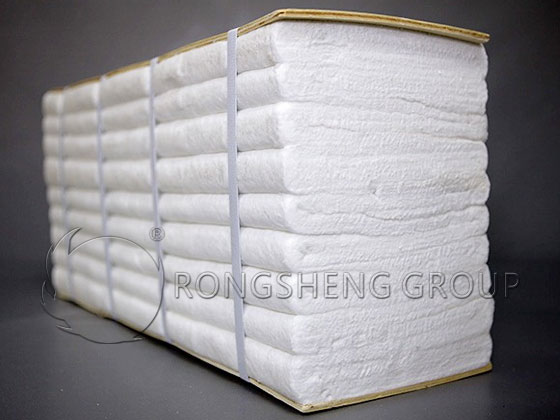
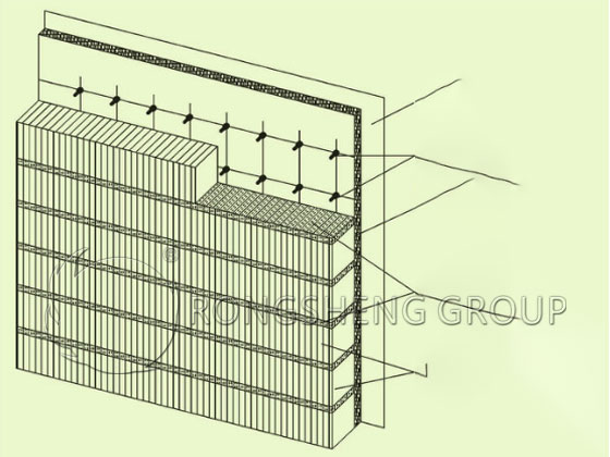
Currently, the furnace lining structure utilizing ceramic fibers in heating furnaces within refining and petrochemical plants primarily consists of a composite assembly comprising ceramic fiber modules (hereinafter referred to as “fiber modules”) and a ceramic fiber backing layer. The installation process for this composite furnace lining structure is as follows:
First, the steel plates of the furnace wall are cleaned and descaled to remove rust.
Second, the furnace wall steel plates undergo anti-corrosion treatment.
Third, layout lines are marked out in accordance with design specifications to determine the precise locations for the anchor studs.
Fourth, anchor studs are welded into place according to the marked layout positions.
Fifth, ceramic fiber blankets are applied to serve as the backing layer.
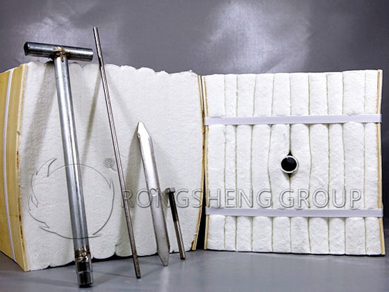
Sixth, the ceramic fiber modules are installed. The central hole of each ceramic fiber module is aligned with a pre-welded anchor stud; using a specialized socket wrench inserted through the central sleeve of the module, the retaining nut is tightened onto the anchor stud. Once all fiber modules have been installed, the packaging straps binding the modules are cut, and the protective plates located on the sides of the modules are withdrawn. Finally, the surfaces of the modules are patted flat to achieve the final formed finish.
The Installation of Ceramic Fiber Modules
Ceramic Fiber Modules and Installation Tools
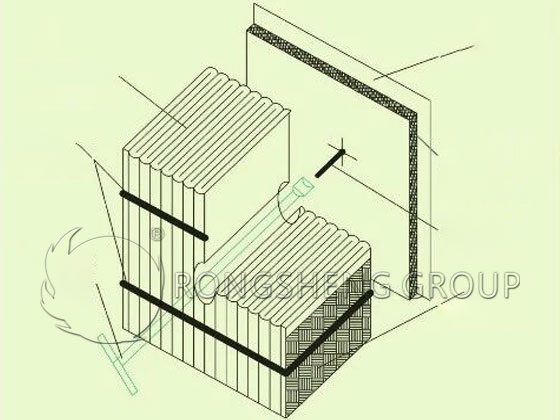
There are two primary structural configurations for composite furnace linings composed of ceramic fiber modules and a ceramic fiber backing: the “Staggered” (or *Pinhua*) arrangement and the “Row-by-Row” (or *Bingpai*) arrangement.
“Staggered” (or *Pinhua*)
“Row-by-Row” (or *Bingpai*)
In the **Staggered Arrangement**, adjacent ceramic fiber modules are installed in an alternating pattern, offset by 90 degrees relative to their direction of folding and compression. Once installation is complete and the binding straps are cut, the ceramic fiber modules expand and rebound in various directions to fill the gaps between them, thereby achieving the final formed structure. However, due to manufacturing tolerances in module dimensions and the phenomenon of uneven expansion at the module corners, gaps can easily form at the junction points between modules; these gaps often become “dead spots” that are difficult to seal or repair. Consequently, the Staggered Arrangement is utilized relatively less frequently.
In the **Row-by-Row Arrangement**, ceramic fiber modules are installed sequentially, aligned according to their direction of folding and compression. The gaps between adjacent rows—specifically in the direction perpendicular to the module’s folding and compression—are filled with pre-compressed ceramic fiber blankets to compensate for potential shrinkage. Currently, this structural configuration is the most widely adopted.
Causes of Damage and Spalling in Ceramic Fiber Furnace Linings
The high-alumina and zirconia-containing ceramic fiber blankets commonly used for furnace linings in oil refining and chemical plants are classified as glassy ceramic fibers; under prolonged exposure to high temperatures, they undergo shrinkage. This phenomenon is inherent to the nature of the ceramic fiber material itself. Microscopically, this shrinkage is attributed to the devitrification (crystallization) and grain growth that occur within the glassy ceramic fibers at elevated temperatures. Glass is formed through the supercooling (rapid quenching) of a molten state. This state does not represent the lowest possible energy state; possessing higher internal energy than a crystalline structure, it exists as a metastable state.
From a thermodynamic perspective, the material exhibits a spontaneous tendency to transition toward a lower-energy state, wherein its constituent atoms automatically rearrange themselves. In other words, it possesses an inherent propensity for devitrification—a transformation into a crystalline state.
From a kinetic perspective, however, the high viscosity of glassy substances at ambient temperatures significantly impedes the rate of internal atomic diffusion and rearrangement. Consequently, the rate of transition from the glassy to the crystalline state is extremely slow, endowing the material with substantial relative stability at room temperature—effectively rendering it a stable state under such conditions.
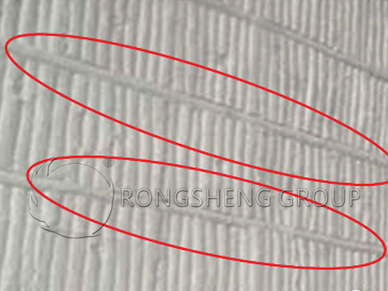
Glassy ceramic fibers are characterized by short-range order but long-range disorder. As the temperature rises, the viscosity of the fibers decreases, atomic motion intensifies, and the rates of atomic diffusion and ordered arrangement accelerate. This shift causes the initial long-range disorder to transition into an ordered arrangement—the process of devitrification. As the ordered, regular arrangement takes shape, the volume of individual ceramic fiber strands contracts. Furthermore, under prolonged exposure to high temperatures, the newly formed crystal grains continue to grow; this growth causes the surface of the ceramic fiber strands to become irregular and uneven—a phenomenon known as “diameter shrinkage.” Persistent diameter shrinkage ultimately leads to a reduction in the length of the ceramic fibers, resulting in overall macroscopic shrinkage of the lining. Once this macroscopic shrinkage occurs, and under the sustained influence of the furnace’s flame atmosphere, the ceramic fiber lining begins to crack and develop fissures. As these fissures appear, flames and hot gas currents seize the opportunity to penetrate the gaps, causing the ceramic fibers on either side of the fissure to come into direct contact with—and effectively become the working surface exposed to—the flames and gas flow. Over time, the ceramic fibers along these contact surfaces continue to shrink in a direction perpendicular to the surface, causing the fissures to progressively widen. Consequently, an ever-increasing volume of flames and hot gases infiltrates the lining, penetrating every available gap and continuously propagating outward in all directions. Upon contact with the anchor pins, the pins undergo oxidation and corrosion under the prolonged influence of high-temperature airflow, eventually fracturing; this, in turn, triggers the detachment of the ceramic fiber modules. Concurrently, the ceramic fiber backing undergoes shrinkage and pulverization, subsequently fracturing and falling away, ultimately resulting in the damage and detachment of the entire ceramic fiber furnace lining.
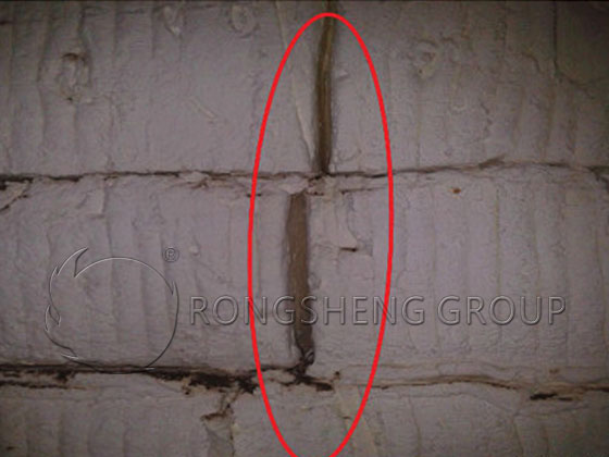
Gaps formed between ceramic fiber modules
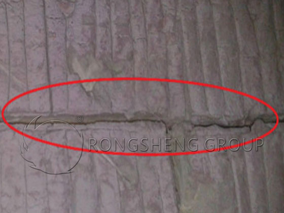
Gaps resulting from shrinkage in the compensation blanket
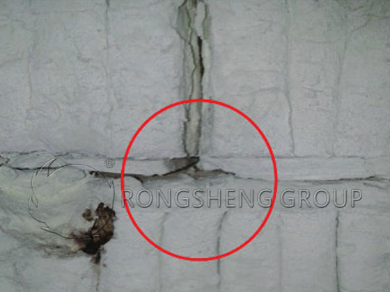
Gaps have formed at the butt joints of the ceramic fiber expansion blankets
Factors Accelerating Damage and Spalling of Ceramic Fiber Furnace Linings—and Corresponding Remedial Measures
1) Material Factors
If the ceramic fiber module materials fail to meet the designed pre-compression ratio requirements—due to insufficient compression during production and packaging, or significant dimensional errors during manufacturing—the subsequent mutual compression generated by expansion and rebound after installation will be insufficient to ensure a tight fit. During furnace operation, under the influence of high temperatures, this premature lack of tightness accelerates the onset of shrinkage and gap formation within the ceramic fiber lining, thereby leading to rapid damage and spalling, and ultimately compromising the service life of the lining. Therefore, strict material acceptance inspections must be conducted prior to construction to ensure that both the quality and dimensions of the materials fully comply with the specified requirements.
2) Construction Factors
First, if the anchor studs are not welded securely, they may detach shortly after the furnace begins operation; this detachment of the anchors inevitably leads to the subsequent spalling of the associated ceramic fiber modules.
Second, inaccurate layout marking—resulting in imprecise or significantly deviated welding positions for the anchor studs—can create uneven spacing between anchors. Consequently, the expansion and rebound forces between adjacent ceramic fiber modules following installation become inconsistent: modules with smaller spacing are compressed tightly, while those with larger spacing remain loosely compressed. During furnace operation, these loosely compressed modules are the first to develop gaps due to shrinkage under high-temperature conditions, thereby prematurely triggering damage and spalling of the ceramic fiber lining. (This results in gaps forming between the modules.)
Third, during construction, attempts to save time and labor may lead to the improper installation of the compensation blankets placed between ceramic fiber modules. If these blankets are not properly folded and compressed—or are merely laid as a single, loosely compressed layer—they fail to achieve the designed compression ratio. This results in insufficient rebound capacity, rendering them ineffective in compensating for thermal shrinkage. Consequently, during furnace operation, gaps rapidly form within the compensation blankets situated between the ceramic fiber modules, ultimately leading to damage and spalling of the furnace lining. (Gaps form specifically at the locations of the compensation blankets due to shrinkage.)
Fourth, if the ceramic fiber compensation blankets are installed using a direct butt-joint method without any special treatment or preparation, gaps will prematurely form at these specific joint interfaces due to shrinkage, thereby leading to damage and spalling of the ceramic fiber furnace lining.
The countermeasures for premature damage and detachment of ceramic fiber furnace linings caused by construction-related factors are as follows:
a) Upon completion of anchor welding, perform a hammer test on each anchor individually to ensure that every anchor stud is fully and securely welded.
b) Marking-out lines must be drawn precisely in accordance with the design dimensions. Anchor studs should be welded at the intersections of the horizontal and vertical lines to ensure accurate positioning and appropriate spacing. If the spacing between certain anchor studs remains somewhat excessive, a visual inspection of the gaps between the ceramic fiber modules should be conducted after installation is complete. For gaps that appear excessively wide, a layer of ceramic fiber blanket should be packed into the gap *before* cutting the module’s binding straps and removing the protective backing plate.
c) During construction, ceramic fiber compensation blankets must be strictly folded in half and compressed, or installed as a double layer. Furnace wall linings should be constructed from the bottom upward, while furnace roof linings should be constructed sequentially from one direction to the other. This approach allows the compensation blankets to be firmly compressed and packed in a specific direction while installing the lower row of modules, thereby ensuring the required compression ratio of the compensation blankets during construction.
d) The method for joining ceramic fiber compensation blankets should be changed from a direct, continuous-seam butt joint to a staggered-seam joint; alternatively, the joint interface should be installed under a certain degree of compression. This prevents the rapid formation of gaps caused by high-temperature shrinkage, which could otherwise allow flame and hot gas currents to penetrate and damage the furnace lining.
3) Human Factors
First, the installation and repair of ceramic fiber furnace linings typically require the erection and dismantling of scaffolding. If workers focus solely on their own tasks without taking care to protect the lining, scaffolding poles may strike or puncture the ceramic fiber material, thereby damaging the lining.
Second, during the routine installation and maintenance of furnace tubes, workers may fail to exercise caution in protecting the ceramic fiber lining, leading to damage and spalling of the material.
Therefore, when entering or exiting the furnace, or while performing other operations, workers must be strictly required to take diligent measures to protect the furnace lining and to avoid damaging the ceramic fiber material to the greatest extent possible.
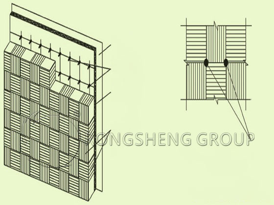
The ceramic fiber compensating blanket is compressed to a high density.
In the corner modules, a layered installation structure is employed.
Repair of Ceramic Fiber Furnace Linings
When a ceramic fiber furnace lining develops shrinkage gaps or suffers damage and detachment after prolonged exposure to high temperatures, immediate repairs are essential to extend the overall service life of the lining and ensure the safe operation of production processes.
1) Repair of Shrinkage Gaps
If a ceramic fiber furnace lining develops gaps exceeding 5 mm in width, immediate repairs are required. Repairs are performed by packing the gaps with ceramic fiber blankets of the same grade. The ceramic fiber blanket must be packed as deeply as possible into the gap until it can no longer be compressed further. It is crucial to ensure that the gap is packed and compressed densely; merely filling the surface is insufficient, as the material will likely detach again shortly after operations resume.
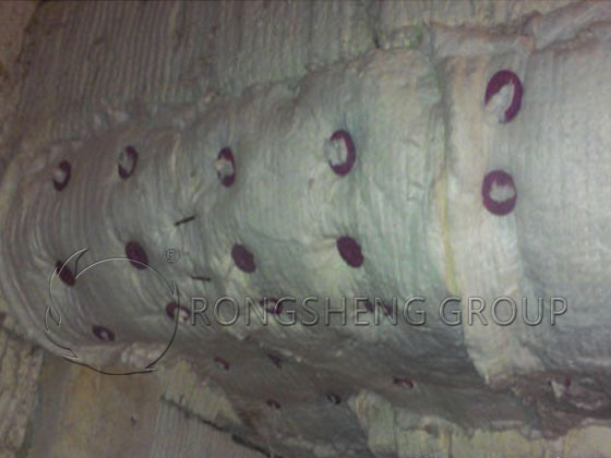
2) Repair of Detached Ceramic Fiber Modules
a) Repair of Detached Standard Ceramic Fiber Modules
When a standard ceramic fiber module becomes damaged and detaches, it should be repaired using a replacement module of the exact same dimensions. A new anchor pin is welded into place at the location of the original anchor point; a ceramic fiber blanket backing is then installed, followed by the installation of the replacement ceramic fiber module. Ceramic fiber blanket material is compressed between the two rows of modules perpendicular to the direction of the module’s internal folding/compression to compensate for shrinkage. Any larger gaps occurring between the newly replaced module area and the surrounding, unreplaced modules should be filled with ceramic fiber blanket material.
b) Repair of Detached Special-Shaped Ceramic Fiber Modules
When a special-shaped ceramic fiber module (such as a corner module, curved module, etc.) becomes damaged and detaches, the repair is performed using a layered installation method with ceramic fiber blankets. This involves welding a long anchor pin into place, then applying ceramic fiber blankets layer by layer until the total thickness matches that of the original furnace lining; finally, the outermost layer is secured using ceramic caps. The reason for switching to a layered ceramic fiber blanket method for these repairs is twofold: firstly, when a special-shaped module becomes damaged and detaches, a corresponding replacement module of that specific shape is often unavailable in stock. Secondly, after the original module detaches, the adjacent—yet still attached—special-shaped modules have typically already undergone prolonged exposure to high temperatures, resulting in shrinkage and a loss of elasticity. If one were to attempt to repair the area using an identical special-shaped module according to the original structural design, the contact interface between the new module and the adjacent, aged modules would lack sufficient compressive density, thereby creating a new potential weak point or hazard. Following high-temperature operation, rapid shrinkage would occur, leading to the formation of gaps and, subsequently, further damage and detachment of the furnace lining. By adopting the layered ceramic fiber blanket structure instead, the blanket material can be cut to dimensions larger than the damaged area, thereby ensuring a more robust and secure repair. In this way, a compression allowance can be provided at the interface with the remaining, unfallen irregularly shaped modules, thereby enabling installation via compression laying and effectively resolving the aforementioned issues. Following the detachment of corner modules—specifically those located at the furnace roof of a cracking furnace and at the lifting-hole corners of a steam superheater within a styrene production unit at a certain petrochemical plant—repairs were successfully executed utilizing this layered-structure approach. Since the repairs, operational performance has been excellent.
How to Maintain Ceramic Fiber Furnace Linings?
1) Ceramic fiber furnace linings undergo shrinkage when exposed to high temperatures. This phenomenon is inherent to the material’s nature and results from crystallization and grain growth occurring at elevated temperatures. High-temperature shrinkage leads to cracking and gap formation within the lining; ultimately, under the prolonged impact of high-temperature flames and gas flows, the lining will deteriorate and detach.
2) Dimensional and mass tolerances inherent to the ceramic fiber material itself—as well as defects in construction quality and human error—can all accelerate the material’s deterioration and detachment, thereby compromising its service life. Consequently, these factors must be given careful attention during installation, inspection, and maintenance operations.
3) When a ceramic fiber furnace lining sustains damage or detachment, repairs should be executed in accordance with the original structural design whenever feasible. In instances where the original material type is unavailable, a layered ceramic fiber blanket structure may be employed to effect the repair.